To shop for parts: Click the tab marked SHOP near the top of any page to visit SV3Power.com/store/.
Many years ago, www.whyturbothat.com motivated me to do two things – properly tune the engine, and document the changes I made and the effect they had on the engine on this page. Orion seems to have moved on to other things but his page really woke me up to the value of objective testing.
I drove my 7A-GE powered MR2 around for almost a year after I got it smogged without really touching it. I guess I just wasn’t really excited about getting into it again, so I left it as it had been. It ran well enough and was entertaining to drive so I felt no great urge to mess with it. Almost on a whim, I decided to look into StreetDyno again. StreetDyno is a free computer program that lets you record a sound file from your ignition system, and then converts that sound file into horsepower and torque curves by comparing your engine’s actual recorded acceleration to the car’s other properties (weight, aerodynamic drag, drivetrain loss, etc). It’s a pretty sophisticated program and even has inputs for weather conditions. Obviously it cannot be used to compare directly with actual dyno numbers, but it is a repeatable, reliable tool for evaluating changes you make to your vehicle without the cost and time of visiting a conventional dyno.
Anyone who wants to try StreetDyno is welcome to download it from me – CLICK HERE – but I don’t have time to provide help with the program. You will need to figure it out on your own. There is a little more info in Part Two that may help.
Ignition impulses can be recorded directly onto any laptop computer as a sound file. I did this with Audacity, a free audio editing program. A couple of people have asked how to connect the laptop to the car so I’ve added a couple of pictures of the voltage divider I built to do that.
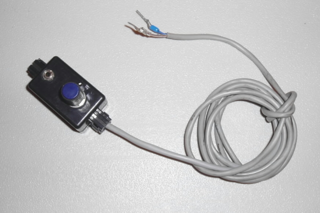
I used a plastic box pulled from a prehistoric car stereo wiring harness. The headphone jack is the same as the one on the laptop so a simple cable from Radio Shack connects the two. The blue wire has a 1/4″ spade connector and goes to the IG- connector on the outside of the diagnostic connector in the engine compartment, and the clear one goes to the E1 (earth) terminal inside the diagnostic connector.
The guts inside the box.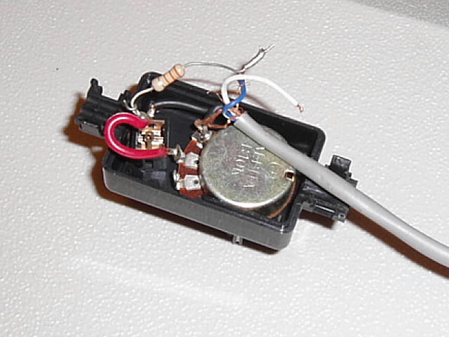
1) Black wire is from mounting ring on headphone jack (i.e. innermost terminal on cable) to one side of potentiometer. This is also connected to the wire that goes to the E1 terminal.
2) Red wire is from center terminal on pot to either of the other terminals on the jack (doesn’t matter which).
3) Resistor is from headphone jack terminal (shared with red wire) to wire connected to IG- terminal. I don’t know whether the orientation of the resistor is important, but it does work in this configuration. Be sure all circuits are insulated from each other to avoid interference (or worse).
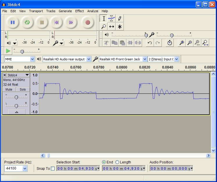
When everything is set up correctly, you should be able to create a .wav file, edit it to cut off everything outside the WOT acceleration run, and end up with something that looks like this:
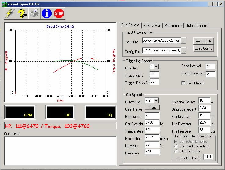
One thing I wanted to do was compare my car to a stock 4A-GE.I wanted to know what my time and money had done for me. Luckily, a co-worker had a bone-stock ’86 MR2 that had just had a recent tune-up. It was running really well, so we made several runs in it. It’s important to make several runs over the same stretch of road at each step; a gust of wind or other factor can really skew your results if you’re relying on only one sample. We weighed the car first and estimated 15% drivetrain loss, since that seems to be a pretty reasonable figure for most cars with a manual transmission. I allowed his car a .33cd since he has the full factory aero kit, vs. .35 for mine with no spoilers. I am trying to be conservative so I don’t artificially inflate the results. Just like the AE86 did years ago, it produced numbers remarkably close to what the factory quoted. And when I changed the drivetrain loss to 0% to simulate wheel horsepower, the numbers pretty closely matched what people usually get with a stock AW11 on a Dynojet. The stock car comes first to establish a baseline.
Stock AW11: 111hp at 6470rpm, 103ft/lb at 4760
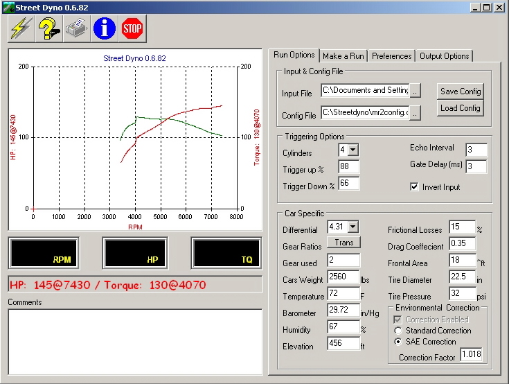
I also weighed my car and tested it.Since it has the same drivetrain, I used the same 15% loss figure. I must say I was both pleased and disappointed with the initial results. I had hoped for more but expected to be more disappointed than I really was.
First run, in as-is configuration: 140hp at 6600, 128ft/lb at 4080

Something to note here: The horsepower curve fell off sharply at redline (7500) unless I trimmed the .wav file back. I trimmed it back until the drop went away, and discovered a big rise in power towards redline. Unfortunately I wasn’t smart enough to investigate more thoroughly, because it turns out to be bogus, some unfortunate accident that does not reflect the engine’s true output. When the peak power starts showing up at lower RPM, you’ll know I have stopped over-trimming the .wav files. Meanwhile, I am listing the actual peak and disregarding the bogus numbers at redline.
The first variable I started testing was ignition timing. This engine detonated since day one, and before converting to MegaSquirt, required some very careful driving to avoid pinging it to death, so I had retarded the timing a few degrees to avoid that. Luckily it didn’t detonate on full throttle, so if it started to rattle, I could usually floor it to make the noise go away. I started with the ignition timing turned way back to TDC and advanced it from there. It liked all of the 9 degrees BTDC I gave it, but I stopped there because the detonation was getting harder to drive around.
Next I messed with intake cam timing. I advanced the intake cam in two-degree increments (degrees of camshaft rotation; each degree at the camshaft equals two degrees at the crank) a total of about 10 degrees from where it had been and realized a huge jump in torque as well as a little horsepower. I also found more detonation, which reminded me why I had retarded the intake cam so much in the first place (to bleed off cylinder pressure on the compression stroke), and this is where I realized that I had been fooling myself with the false horsepower peaks at redline. The torque curve was getting stronger from 2000 RPM on up and was very flat, and it was exciting to see the results start coming in! At this point the idle was starting to get just a tiny bit choppy, though drivability was totally unaffected.
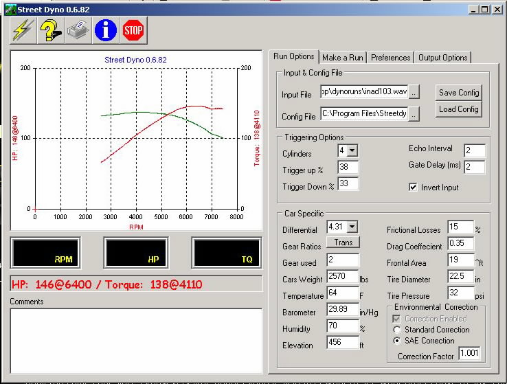
Notice there’s still a little lump after 7000 RPM. Let’s ignore that and look at power up to that point.
I decided to retard the ignition timing back to five degrees BTDC to help reduce detonation. The peak numbers didn’t drop much, but torque fell by two to three ft/lb everywhere around the peak. That brings up another point: when the torque curve is very flat near the peak, StreetDyno seems to pick an arbitrary point on the RPM scale, anywhere within that flat area, to label as the torque peak. In other words, if the engine produces 140 fl/lb of torque between 4100 and 4450 rpm, it’s anyone’s guess what the program will call the peak. But since you can hover the cursor over the graph and get horsepower and torque readings at any RPM, it’s not a big deal.

As an experiment, I tried disconnecting the TVIS system so that it would remain open all the time. Strangely, this helped reduce detonation, but it also definitely reduced torque below the 4400 RPM crossover point.

Oddly, adjusting the exhaust cam two degrees in either direction seemed to do nearly nothing, so I left it alone for the time being.
For more, see Chapter Two.