To shop for parts: Click the tab marked SHOP near the top of any page to visit SV3Power.com/store/.
The 7A crank has six flywheel bolts and requires a 4A-FE or 7A-FE flywheel. I used a 7A-FE flywheel and cheap LUK clutch. It has held up adequately but never really had a firm bite. There’s a lightweight chromoly flywheel and more aggressive clutch waiting to be installed along with a C160 six-speed transmission, only a few of many parts on the Someday shelf.
Another note: Some people berate the 7A crank for having only six flywheel bolts. This does not become a weakness unless exposed to several hundred horsepower. They use the exact same bolt as the T-series engines (2T-G, 3T-C, 3T-GTE, etc), which also only use six, and nobody questions them. ARP offers flywheel bolts for the T motor if you don’t trust the OEM parts.
The lower alternator bracket mounts to the block and the upper one mounts to the head. To reach the alternator, the upper bracket had to be extended vertically by about 15mm because the 7A block is taller by about that distance. This was accomplished by cutting the inboard (engine) end of the bracket out and splicing in a rectangular piece of steel of the same thickness as the bracket. The alternator fits and adjusts just like stock.
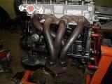
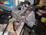
The exhaust system gets tricky with a 7A-GE. The stock AW11 manifold is not a bad piece, but it doesn’t clear the 7A-FE’s two-piece oil pan. Aftermarket headers were all fairly expensive, if even available, and many didn’t have a good reputation. I decided to try a 20V Silvertop (AE101) header. A 20V header needs the two end bolt holes relocated to fit a 16V head. I drilled a new #1 hole (near the front end of the engine) and cut off the end of the other end of the flange, flipped it over, and re-welded it to place the #5 bolt hole in the correct position for the 16V head.
The 20 valve header is a nice piece, but it didn’t clear the starter motor. I could either modify the header to provide more clearance, or replace the transmission with a later version that accommodates a starter on the intake side of the block. Extending the header seemed like the best plan. The hardest thing was finding the unusual 1.375″ OD tubing. A local welder who occasionally builds exhausts for motorcycles and karts gave me a scrap of the correct tubing and I started by cutting off the flange, then tacking in 1.25″ long extensions.
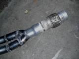
After extending the header it was time to build the downpipe. This was a few years before I started building 20V adapter downpipes, and I didn’t have any flanges, so I welded the downpipes to the header. A 1.75″ OD mandrel bent U-bend was cut it in two pieces to create the downpipes, and the the leftover straight sections were added after the bends for a little extra length. The collector was made from the little leftover pieces of curved 1.75″ tubing and a piece that goes from 2.0″ OD to 2.25″ ID, sort of a poor man’s merge collector.
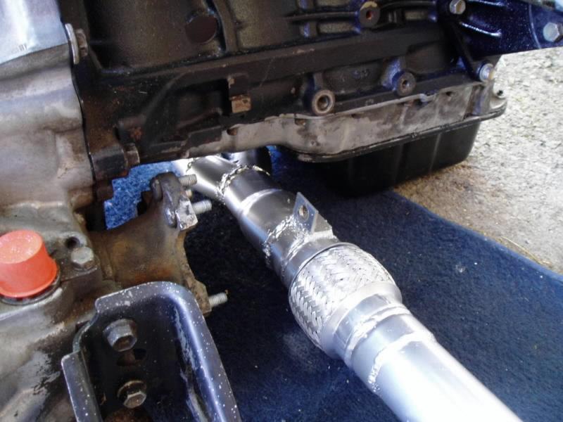
All this produced very crude-looking 4-2-1 header that clears the oil pan perfectly, and was all set up for a 2.25″ OD exhaust system. Trying to weld it up neatly with flux-core wire was a nightmare. I added some brackets to bolt the header to the block at the bottom of the top half and at the back of the block near the flex joint, then added a bung for the EGR port onto the #4 tube, and finally built a crossover pipe at the top of the downpipes, where they join the primaries, to give the oxygen sensor somewhere to mount. This turned out to be a poor location for the sensor, since it sat in a pocket of slow moving exhaust gas, and I later relocated it to the collector area.
After having the flange ground flat again and relocating a couple of heatshield mounts, the header got a coat of Duplicolor High Heat ceramic paint (DH 1606). I learned the hard way that anything more than a thin coating will burn off immediately on startup and make an ugly, blistering, stinking mess. After the header was built I chopped up some aluminum to form a heatshield. Lots of adjusting was necessary to get the heatshield to clear the shifter cables once the engine was installed.
After mating the engine and transmission I realized that I should have paid more attention when building the header. The right side axle wanted to pass right through the pipe after the collector. After assembling the car I decided to just cut and modify the header to kick to the right after the collector to avoid the CV boot.
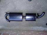
The catalytic converter had previously been replaced with a cheap aftermarket one which had broken apart inside, so I very carefully cut away the flanges and enough of the inlet and outlet that I could stick a plain 2.25″ pipe through the shell as a temporary solution. The rest of the exhaust system was built of 2.25″ OD mandrel bends, a used (cheap) Magnaflow muffler and an OEM-style resonator from eBay, all painted black with more Duplicolor High Heat paint. The muffler had to be installed at an angle to clear the cat. It fit great but was ear-splittingly harsh and loud at high RPM. The resonator was later replaced with another Magnaflow just like the first one and a cheap glasspack was added where the catalytic converter had been. That worked as a temporary solution to kill the buzz and rasp.
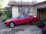
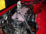
MR2 engines go in and out from below, so we lifted the tail end of the car so that the engine could be stuffed beneath it. Doing this without a lift was a pain. It was hard as hell just lifting the car up high enough to get the engine under it, and kicking the engine-tranny combo under the car on my creeper was a battle. Once the engine was under the car it had to come up to the mounts, which was incredibly frustrating. Trying to find the right angles to get it into place without breaking anything important made for a very long evening.
The first set of injectors I tried were yellow 295cc units from a 7M-GE. The connectors are different from the square ones the stock injectors used, so I cut the ends off the stock harness and spliced in the new connectors. The wires were stripped, twisted together, soldered and covered in heatshrink, and finally wrapped in self-sealing tape.
Once installed and connected, the thing fired up easy and sounded healthy. The idle was a little choppy but the car still drove like a kitten. There were a few piddly problems to work out, like part-throttle detonation unless the timing was set at least five degrees back of where it was supposed to be. Retarding the intake cam also helped bleed off enough cylinder pressure to avoid detonation. The car also wanted a new oxygen sensor. Other than that it was pretty much good to go.
With the Web cams in, the car was nowhere near clean enough to pass a smog test. With the wrong injectors, wrong cams, too much compression, and no cat, I was not that surprised. I put the stock cams and cat back in and played with a few parameters and we got it clean enough to pass. After driving and tweaking it for a year and a half, it was plenty drivable, but still ran rich and still detonated on part throttle. For that reason I ended up converting to MegaSquirt setup from diyautotune.com (highly recommended) and have been very happy with the results.